

 Deutsch
 English
 français
 español
 العربية
 中文
中文
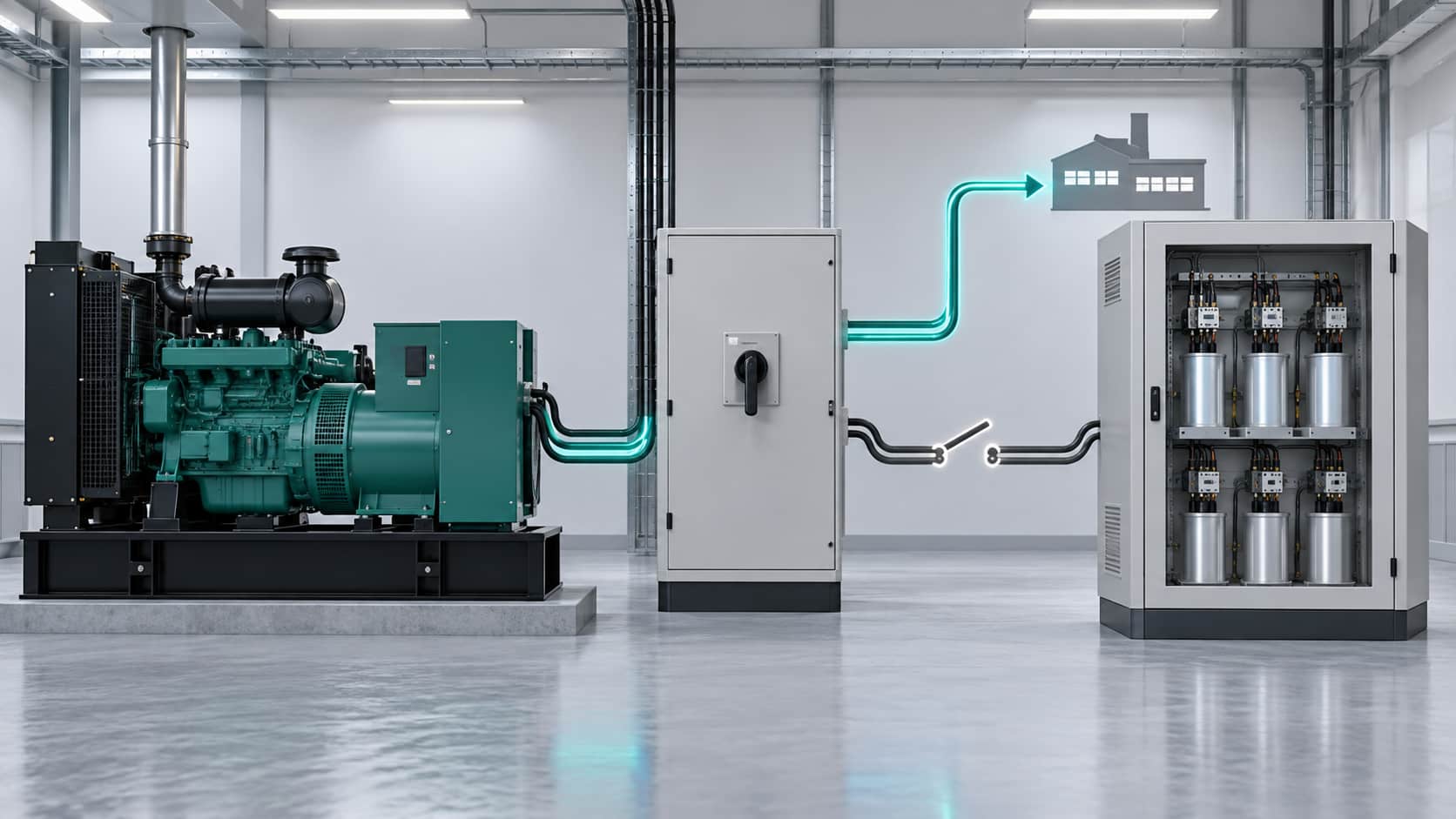
An automatic power factor correction (APFC) panel may work normally on utility power. During an outage, the transfer switch connects a standby generator, leaving that panel on a very different electrical source.
If capacitor steps switch at the wrong time, the generator may see leading power factor, unstable voltage, or reverse reactive-power flow. APFC controls designed for utility conditions may be unsuitable on generator power.
Many manufacturers require the bank to disconnect during generator operation. Any exception needs manufacturer approval and a site-specific engineering review.
APFC switches capacitor stages to supply reactive power for inductive loads. The utility is usually a strong voltage source; a standby generator has less ability to absorb excess capacitive reactive power or handle sudden changes.
Outage loads also differ. Nonessential equipment may shut down, motors may start in another sequence, and the generator may initially carry little load. A utility-sized capacitor step can be excessive under these conditions.
The controller may still command a stage, but that does not establish generator compatibility.
If connected stages supply more reactive power than emergency loads need, the generator sees a leading load, sometimes shown as negative or reverse kVAr. The alternator or voltage regulator may struggle, and protection may trip.
The risk increases at light load or when a large motor stops but its capacitor steps stay connected.
Capacitor switching changes reactive power abruptly. On a generator, the voltage response may be greater than on utility supply. It depends on alternator design, step rating, and connected loads.
Repeated stage switching also adds to normal motor starts and load pickup.
Source impedance changes after transfer. Capacitors can interact with system inductance and harmonics from drives, UPS units, and rectifiers. A bank acceptable on utility supply may behave differently on the generator.
Detuned reactors may address resonance, but not leading power factor or generator compatibility.
| Operating stage | What may happen if APFC stays active | What the design should verify |
|---|---|---|
| Utility supply before outage | Capacitor steps follow normal plant demand | Normal target, step sizes, and harmonic conditions |
| Transfer to generator | Previously connected stages remain on or reconnect | All required stages disconnect before generator pickup |
| Generator running at light load | Capacitors exceed the remaining inductive demand | Generator kVAr, power-factor direction, and voltage |
| Emergency loads start or stop | Controller switches large stages during load changes | Generator response and any approved generator-mode logic |
| Return to utility | APFC resumes before the source and load stabilize | Reconnection sequence and controller restart behavior |
The bank's state matters throughout transfer, not only during steady operation.
For many standard installations, yes. The APFC bank should be inhibited before transfer, following its manufacturer's instructions. Some products provide a generator-status input for this purpose.
Transfer-switch status may form part of the interlock, but qualified personnel must design and verify its timing. Do not assume the APFC controller recognizes a source change by itself.
Review the return to utility as well: stages should reconnect only after required conditions are restored.
The control scheme should use a dependable indication of which source is supplying the facility. When generator operation is expected, it should prevent unauthorized capacitor stages from connecting and confirm that stages already connected have released. It should remain effective throughout the outage, even as essential loads start and stop.
When utility power returns, the system should follow the equipment's reconnection sequence rather than immediately applying every available stage. An alarm or status indication can help operators identify a bank that failed to disconnect as intended.
The method varies by panel and transfer equipment. Some manufacturers provide a dedicated generator input; others specify an external control arrangement. The purpose is a verified change of operating mode, not simply a manual instruction to remember during an emergency.
Sometimes, but it needs deliberate engineering. Large motors may impose enough reactive demand to limit generator kVA. Limited compensation may help if the generator manufacturer permits it and controls prevent leading power factor.
The engineering review should establish:
The generator's permitted leading and lagging power-factor range
Minimum and maximum emergency-load kW and kVAr
The smallest capacitor step that can be connected safely
Whether stages are blocked during transfer and motor starting
Voltage-regulator behavior when stages connect or disconnect
Harmonic and resonance conditions in generator mode
How the panel responds to a fault or loss of generator-status signal
The outcome may be to keep APFC off, permit selected stages, change load sequencing, or use another engineered device. An SVG offers variable compensation but also requires generator-specific compatibility checks.
An APFC-related issue may appear as voltage rising just after transfer, repeated capacitor-stage switching, a sudden shift to leading power factor, or a generator alarm associated with reactive power. A problem may also occur when a large motor shuts down and leaves capacitors connected to a much smaller remaining load.
These signs do not prove the APFC bank is the sole cause. Compare the generator event log, controller commands, stage feedback, and electrical measurements at the same time. That timeline is more useful than adjusting the power-factor target based on one display reading.
Review the generator and APFC manuals, then confirm what happens to every stage during a controlled transfer test.
Record voltage, frequency, kW, kVAr, power-factor direction, and stage status at transfer, light load, load pickup, and return. Correct any sequence that conflicts with the manufacturer's instructions.
Only qualified personnel should perform this work. Capacitors can retain a dangerous charge, and the controller display does not prove isolation.
Not without checking both manufacturers' instructions. Many installations require a generator-mode inhibit or disconnection.
Not always. Utility penalties are irrelevant during generator operation, but generator capacity and voltage still matter. Add correction only if the design permits it.
No. Detuning addresses a particular resonance risk. It does not by itself prevent overcompensation, reverse kVAr, or an unsuitable capacitor-switching sequence.
No. SVG is more flexible, but its compatibility with the alternator, voltage regulator, and load still requires study.
An APFC panel that performs well on utility power should not automatically switch stages on generator supply. Emergency loads and generator capability differ from normal service.
Follow manufacturer instructions, verify the transfer interlock, and measure each operating stage. If compensation is needed, design it specifically for generator mode.
YT Electric can review your APFC panel, generator-mode measurements, and transfer sequence to help identify a suitable power-factor correction arrangement for both normal and backup operation.



 IPv6-Netzwerk unterstützt