

 Deutsch
 English
 français
 español
 العربية
 中文

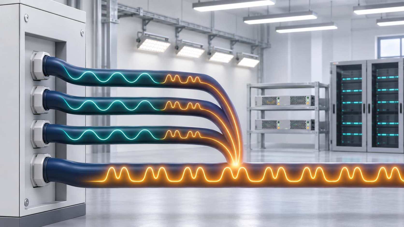
Three-phase equipment is designed to operate from three voltages that are close to equal. Unequal single-phase loads, poor connections, conductor differences, or supply problems can make one phase voltage differ from the others.
This is voltage unbalance. A small difference can produce much greater motor current unbalance, increasing heat and reducing usable capacity. Diagnosis matters because an SVG and a repaired connection solve different problems.
Voltage unbalance means the three phase voltages are unequal. It is normally assessed using all three line-to-line voltages, although the required method depends on the applicable standard.
A common field calculation is:
Voltage unbalance (%) = maximum deviation from the average voltage ÷ average voltage × 100
For example, if the measured voltages are 400 V, 397 V, and 391 V, the average is 396 V. The largest deviation is 5 V, giving approximately 1.26% unbalance by this method.
Some instruments calculate the ratio of negative-sequence to positive-sequence voltage. The methods differ, so compare measurements using the same definition.
Voltage and current unbalance are different. Unequal voltage can cause unequal current, but motor winding, impedance, or mechanical problems can unbalance current when supply voltage is balanced.
Lighting, heaters, chargers, and other phase-to-neutral loads may not be evenly distributed. The heaviest-loaded phase can experience greater voltage drop.
Load patterns change, so a balanced panel may become unbalanced when other equipment starts.
A loose terminal, worn contact, damaged cable, or corroded joint adds impedance to one phase. Its voltage drop becomes more visible as current rises.
A blown fuse or open conductor causes phase loss or single-phasing. This requires immediate fault investigation, not ordinary unbalance correction.
Different conductor sizes or lengths, poor parallel-cable sharing, or dissimilar terminations can create unequal drops, particularly on long or high-current feeders.
Transformer winding issues, loading, tap settings, or the upstream network may affect voltage before it reaches the facility. Unbalance at the incomer and multiple feeders suggests an upstream source.
Welders and other fluctuating loads can cause dynamic unbalance. A spot measurement may miss it, so trend recording is more useful.
| What you observe | Possible cause | What to check first |
|---|---|---|
| One line voltage falls mainly under heavy load | High-impedance joint or undersized conductor | Measure upstream and downstream voltage; inspect the affected phase |
| Unbalance appears at the main incomer and several feeders | Transformer or utility-side condition | Record incoming voltage over time and compare with supply requirements |
| Only one motor circuit is affected | Cable, fuse, contactor, connection, or motor issue | Measure at the MCC output and motor terminals |
| Voltages are balanced but motor currents are not | Motor winding, connection, or mechanical problem | Compare winding resistance, motor condition, and load |
| Unbalance changes with single-phase load operation | Uneven phase loading | Log phase voltage, current, kW, and operating states |
| One phase is missing or extremely low | Blown fuse, open conductor, or failed contact | Isolate equipment and investigate phase loss immediately |
Measurements at several points separate supply issues from local faults. Use qualified personnel for energized work.
Unbalanced voltage creates a negative-sequence magnetic field that opposes normal motor rotation. Current unbalance can be substantially greater than the voltage percentage.
Additional current increases winding losses and rotor heating. A motor may run hot even when average current appears acceptable.
Unbalance can reduce torque and increase vibration. The motor may need derating because normal nameplate load could exceed its thermal capability.
Motor protection or variable-speed drives may trip when voltages or currents become uneven. Without suitable protection, repeated overheating can damage insulation and equipment.
Measure all three line-to-line voltages simultaneously. For changing loads, use a three-phase power-quality analyzer rather than three separate multimeter readings.
Compare the incoming supply, switchboard, feeder, motor control centre, and equipment terminals. A change between two points localizes the fault. Unbalance at the incomer directs attention to the transformer or utility supply.
Record phase current, active power, and operating conditions alongside voltage. Current unbalance alone does not prove voltage is the root cause.
After safe isolation, inspect fuses, contactors, cable joints, and terminals. Thermal scanning can identify hot connections but does not replace electrical testing.
The solution should target the confirmed source:
Redistribute single-phase loads more evenly across the three phases.
Repair loose connections, damaged conductors, worn contacts, and faulty fuses.
Correct unequal cable sizes, lengths, terminations, or parallel-cable sharing.
Review transformer loading, connections, and tap settings.
Separate or reschedule large fluctuating single-phase loads where practical.
Install phase-monitoring protection for phase loss, reversal, and excessive unbalance.
Ask the utility to investigate when the unbalance is present at the point of supply.
A three-phase capacitor bank supplies reactive power. It does not repair a connection or automatically equalize phase voltage, and incorrect application can cause resonance or overcompensation.
A four-wire SVG can balance phase currents and compensate reactive power when uneven downstream loading is the cause. It cannot restore a missing phase, repair a cable, or remove an upstream source problem. Measure first, then select equipment.
No. Voltage unbalance describes unequal supply voltages, while current unbalance describes unequal phase currents. Voltage unbalance can produce current unbalance, but motor, cable, or load problems can also make currents unequal.
Yes. A relatively small voltage unbalance can create a much greater current unbalance and additional motor heating. Acceptable limits and any required derating should follow the motor manufacturer, protection settings, and applicable standards.
Usually not. A balanced capacitor bank corrects reactive power but does not independently control each phase or repair supply faults. Unbalanced compensation requires careful engineering and should not be used to conceal a defective connection.
A suitable four-wire SVG can help balance phase currents caused by unequal single-phase loads while also compensating reactive power. It cannot correct an open phase or a voltage imbalance originating from the upstream supply.
Voltage unbalance may begin with unequal loads, excessive impedance in one phase, a poor connection, or an upstream supply condition. For motors, the resulting current unbalance can cause extra heat, reduced torque, nuisance trips, and loss of usable capacity.
Measure all three voltages simultaneously and compare several distribution points before choosing equipment. Repairs, load redistribution, phase protection, utility action, and dynamic compensation address different causes.
YT Electric can review your three-phase measurements, load profile, motor behaviour, and distribution arrangement to help identify the source of unbalance and determine whether load balancing, protection, capacitor compensation, or an SVG is appropriate.



 IPv6-Netzwerk unterstützt