

 Deutsch
 English
 français
 español
 العربية
 中文
中文
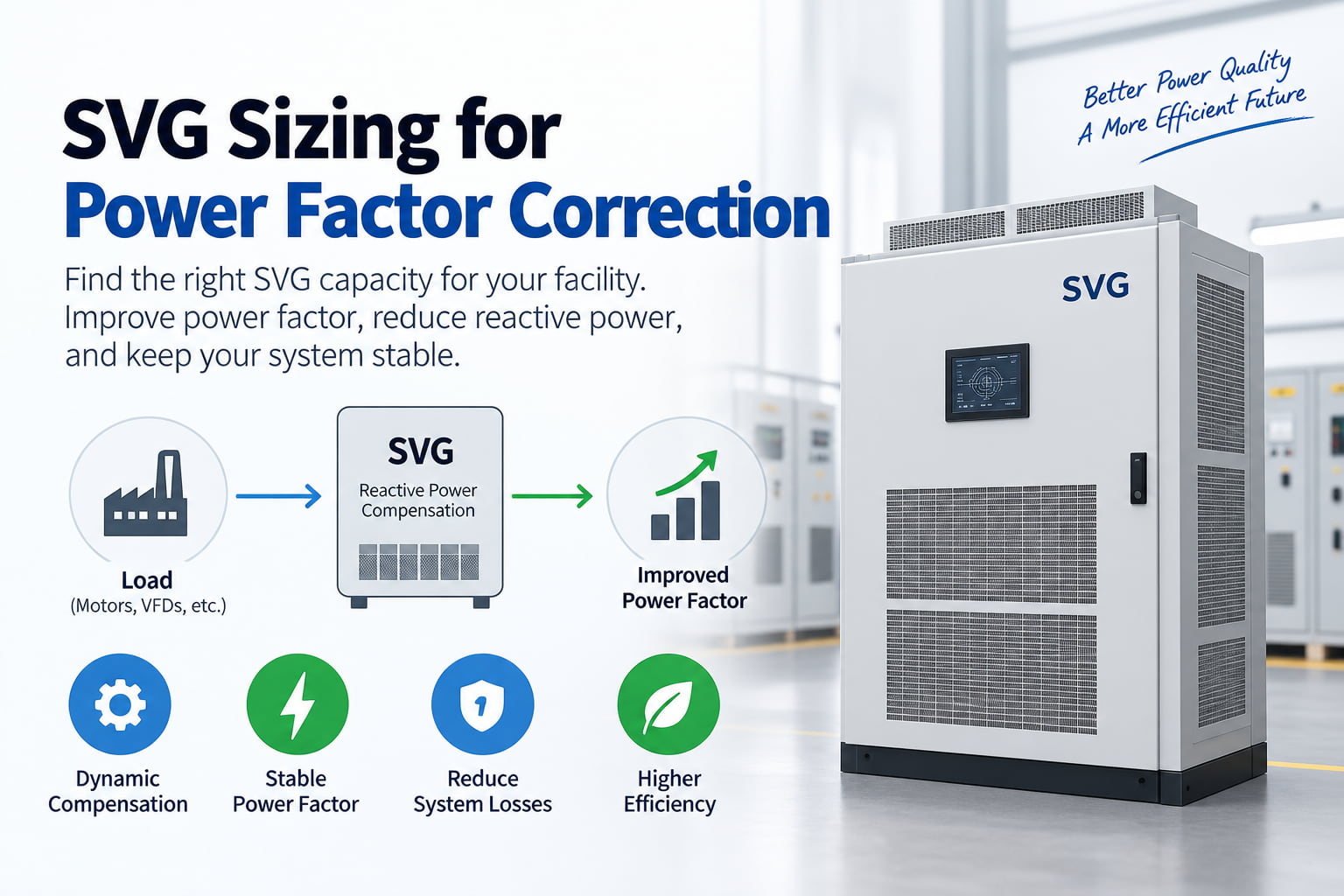
SVG sizing is the first step in choosing the right Static Var Generator for power factor correction. If the SVG is too small, the power factor may remain low. If it is too large, the project cost increases without adding real value.
An SVG, also called a Static Var Generator, provides dynamic reactive power compensation. It improves power factor by injecting or absorbing reactive power in real time. This makes SVG more suitable than a traditional capacitor bank in systems with changing loads, unstable power factor, or fast reactive power demand.
Correct SVG sizing should be based on the real reactive power requirement of the site, not only on transformer capacity or total load current.
SVG sizing means choosing the correct kvar rating for the Static Var Generator.
SVG systems are usually selected in kvar, such as:
50 kvar SVG
100 kvar SVG
150 kvar SVG
200 kvar SVG
400 kvar SVG
600 kvar SVG
1000 kvar SVG or higher
This rating shows how much reactive power the SVG can compensate.
For example, if a facility needs 180 kvar of reactive power compensation, a 200 kvar SVG may be suitable. If the load changes often or the site plans to expand, a larger SVG capacity may be safer.
The goal of SVG sizing is simple: match the SVG capacity to the actual reactive power demand.
Power factor shows how efficiently electrical power is being used. A low power factor means the system draws more current than necessary to deliver the same useful power.
Poor power factor can cause:
Higher current
Higher cable losses
Transformer heating
Reduced usable system capacity
Utility penalties
Voltage instability
Lower energy efficiency
Many industrial sites use motors, pumps, compressors, welders, elevators, HVAC systems, and production equipment. These loads often require reactive power. Without proper power factor correction, the electrical system works harder and becomes less efficient.
SVG helps correct reactive power in real time and keeps the power factor closer to the target value.
A common mistake is sizing SVG only from transformer capacity.
For example, a site with a 1000 kVA transformer does not automatically need a 1000 kvar SVG. The transformer rating shows system capacity. It does not show the actual reactive power demand.
Two sites can have the same transformer size but very different power factor problems.
One factory may have mostly stable loads and only need 200 kvar compensation. Another factory may have fast-changing motor loads and need 500 kvar compensation.
SVG sizing should be based on:
Active power
Existing power factor
Target power factor
Reactive power demand
Load variation
Future expansion
Site operating condition
Transformer size is useful background information, but it is not enough for final SVG selection.
The basic calculation for power factor correction is based on active power and the difference between the existing power factor and the target power factor.
The simplified formula is:
Required kvar = kW × (tan φ1 - tan φ2)
Where:
kW = active power of the load
φ1 = angle of existing power factor
φ2 = angle of target power factor
In practical projects, engineers usually need three main values: existing power factor, target power factor, and active load power.
Example:
A factory has:
Load power: 500 kW
Existing power factor: 0.75
Target power factor: 0.95
The required reactive power compensation is about 276 kvar.
In this case, a 300 kvar SVG may be selected. If the load changes often, a larger SVG or modular design may be considered.
A facility has several motors, pumps, and production machines.
Measured data:
System voltage: 400V
Active power: 600 kW
Existing power factor: 0.78
Target power factor: 0.95
Load condition: changing during production
The calculated compensation demand is about 300 kvar.
A 300 kvar SVG may meet the basic requirement. But if the load changes quickly or future expansion is planned, a 400 kvar SVG may be a better choice.
The final decision should not depend only on the calculation. It should also consider site operation, load changes, and power quality conditions.
Traditional capacitor banks work in steps. They switch capacitor stages on and off according to reactive power demand. This can work in stable systems.
Many modern facilities do not have stable loads.
Loads may change because of:
Motor starting and stopping
Variable frequency drives
Production line changes
Welding machines
Elevators
Solar inverter output changes
HVAC operation
Pump speed changes
In these conditions, reactive power demand changes quickly. A capacitor bank may respond too slowly or overcompensate. It may also create switching stress or resonance risk in harmonic-rich systems.
SVG provides dynamic compensation. It adjusts reactive power output in real time, which helps keep the power factor stable under changing load conditions.
| Item | SVG | Capacitor Bank |
|---|---|---|
| Compensation type | Dynamic | Step-based |
| Response speed | Fast | Slower |
| Best for | Changing loads | Stable loads |
| Overcompensation risk | Lower | Higher |
| Harmonic environment | Safer than standard capacitors | May need detuned reactor |
| Maintenance | Lower | Contactors and capacitors need checking |
| Accuracy | High | Limited by step size |
A capacitor bank is still useful in many simple systems. But for sites with fast load changes, unstable power factor, or harmonic distortion, SVG is often the stronger solution.
For a deeper comparison, add an internal link to: Capacitor Bank to SVG: Why More Facilities Are Upgrading .
Before selecting SVG capacity, engineers should collect the right site data.
Important information includes:
System voltage
Frequency
Transformer capacity
Active power in kW
Apparent power in kVA
Existing power factor
Target power factor
Load type
Load variation
Existing capacitor bank condition
Harmonic distortion level
Future expansion plan
Installation location
3P3W or 3P4W system
The most important values are active power, existing power factor, target power factor, and load variation.
If the site has both poor power factor and harmonic distortion, engineers may need ASVG or SVG with harmonic compensation instead of a standard SVG.
The most common SVG sizing mistakes are:
Sizing only from transformer capacity
Ignoring real power factor measurement
Ignoring load changes
Choosing the same kvar as the existing capacitor bank without checking demand
Ignoring future expansion
Ignoring harmonics
Using a fixed capacitor bank when the load is dynamic
Not confirming 3P3W or 3P4W system type
These mistakes can lead to poor correction results, unstable power factor, overcompensation, or unnecessary project cost.
| Question | Why It Matters |
|---|---|
| What is the system voltage? | Confirms SVG voltage rating |
| What is the active power in kW? | Needed for kvar calculation |
| What is the existing power factor? | Shows current reactive power problem |
| What is the target power factor? | Defines compensation target |
| Does the load change frequently? | Helps determine SVG margin |
| Is there an existing capacitor bank? | Checks replacement or upgrade needs |
| Is harmonic distortion present? | Checks if AHF or ASVG is needed |
| Is expansion planned? | Helps avoid undersizing |
| Is the system 3P3W or 3P4W? | Confirms wiring configuration |
SVG sizing is based on active power, existing power factor, target power factor, and reactive power demand. The basic calculation is required kvar = kW × (tan φ1 - tan φ2).
Yes. SVG can replace a capacitor bank in many power factor correction projects, especially where loads change quickly or the power factor is unstable.
SVG is better for changing loads, fast compensation, and accurate power factor control. Capacitor banks can still work well in stable systems with predictable reactive power demand.
The main data needed includes system voltage, active power, existing power factor, target power factor, load type, load variation, harmonic level, and future expansion plan.
No. Transformer capacity alone is not enough. SVG sizing should be based on the actual reactive power compensation requirement.
Correct SVG sizing is essential for effective power factor correction. The SVG capacity should be based on real reactive power demand, not only on transformer size or total load current.
A proper SVG sizing review should check active power, existing power factor, target power factor, load variation, harmonic distortion, system voltage, and future expansion.
For factories, commercial buildings, mines, water treatment plants, and renewable energy systems, SVG provides fast and accurate reactive power compensation. It helps improve power factor, reduce system stress, lower losses, and support stable long-term operation.
For projects with unstable power factor, changing loads, or uncertain kvar demand, correct SVG sizing helps avoid undersizing, overcompensation, and unnecessary equipment cost.



 IPv6-Netzwerk unterstützt