

 Deutsch
 English
 français
 español
 العربية
 中文
中文
In heavy industry, large data centers, and plants packed with VFDs and six-pulse rectifiers, a distribution transformer can run within its nameplate kVA and still develop abnormal temperature rise, oil-temperature alarms, or accelerated winding insulation ageing. The usual load-current check misses the frequency content of that current. A waveform with modest rms current can carry substantial high-frequency energy, concentrating heat in conductors and metallic structures that the nameplate rating does not directly describe.
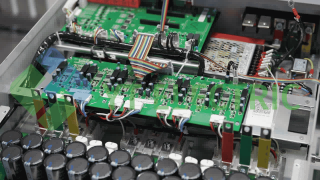
transformer secondary-bus harmonic mitigation layout.
At the fundamental frequency, copper loss follows the familiar I2R relationship. For a distorted current, the rms value alone is insufficient because each harmonic sees a different electromagnetic environment. The fundamental component produces the expected load loss, but harmonic components increase both resistance and field-related loss. The thermal result depends on conductor geometry, leakage flux, cooling class, load profile, and the duration of the overload condition.
Winding Eddy Current Losses are induced by leakage flux penetrating conductors. A practical screening relationship is proportional to Ih2h2, where h is harmonic order. Thus, a 5th-harmonic current receives a frequency multiplier of 25 and a 13th-harmonic current a multiplier of 169 before conductor and construction factors are considered. The loss may be concentrated near strand edges, transposed-conductor boundaries, and axial ends of windings. Those local hot spots can age insulation faster than the average winding temperature suggests.
Stray load losses add another path. Leakage flux induces currents in tank walls, clamps, tie plates, bus supports, and other structural steel. The resulting heat is not always visible in a standard efficiency calculation. Core hysteresis and core eddy-current losses also increase when voltage distortion or excessive volts-per-hertz conditions are present, although current-driven winding and stray losses usually dominate the overheating complaint in a rectifier-fed installation.
Third, ninth, and fifteenth harmonics are zero-sequence components in a three-phase, four-wire system. They add in the neutral rather than canceling. A neutral conductor, delta winding, or closed circulating path can therefore carry a large triplen current. The resulting zero-sequence current produces additional copper, eddy, and structural heating. A transformer with a high neutral burden can alarm even when phase rms current appears balanced. Measure the neutral and not only the three phase conductors.
The commonly used K-Factor index is calculated as K = ∑ Ih2h2, with harmonic currents expressed as per-unit values of the rated fundamental current. K-1 describes a standard transformer designed primarily for sinusoidal load. It does not mean the transformer immediately fails when harmonics exist; it means the thermal design does not include a specified harmonic-loss allowance. The actual limit must come from the manufacturer, temperature-rise test, cooling arrangement, and measured duty cycle.
K-4, K-13, and K-20 transformers use larger conductors, improved winding construction, shielding, or additional thermal margin to tolerate defined nonlinear-load profiles. They are a valid passive design choice when a new facility has a stable and well-characterized harmonic load. The trade-offs are substantial: more copper and steel, larger footprint, higher purchase cost, higher no-load and load losses, and a replacement project that may require shutdown, rigging, and new protection coordination.
For an existing K-1 transformer, operators often impose a 30%–50% capacity reduction as a conservative operating rule. That protects average temperature but wastes installed capacity and does not remove the harmonic current flowing into switchgear, cables, capacitors, and generators. De-rating is a risk-control measure, not harmonic mitigation.
| Loss or effect | 3rd | 5th | 7th | 11th | 13th | K-Factor sensitivity |
|---|---|---|---|---|---|---|
| Fundamental winding I²R | Low direct effect | Low direct effect | Low direct effect | Low direct effect | Low direct effect | Baseline rms current |
| Winding eddy current | Medium | High (h²=25) | High (h²=49) | Very high (h²=121) | Very high (h²=169) | Direct h² weighting |
| Stray load loss | Medium | High | High | Very high | Very high | High sensitivity |
| Neutral/zero-sequence heating | Very high | Low | Low | Low | Low | Neutral path critical |
| Core hysteresis/eddy loss | Low to medium | Medium | Medium | Medium | Medium | Voltage spectrum dependent |
An Active Harmonic Filter (AHF) installed on the transformer low-voltage secondary bus or PCC measures load current and dynamically injects an equal, opposite harmonic current. The transformer then supplies a waveform with substantially lower distortion. Correctly engineered systems can reduce transformer-side THDi to below 5% at the measured PCC, subject to the source impedance, load spectrum, CT arrangement, and available filter current. This is the practical path to meeting an applicable IEEE 519 current-distortion limit; the exact limit and demand interval must be verified for the facility connection.
The benefit is thermal, not merely compliance-related. Lower harmonic current removes the high-frequency component of winding eddy loss and reduces stray flux heating. A transformer operating within its original thermal envelope can recover close to 100% of its nameplate capacity, avoiding a premature replacement. The AHF also protects cables, neutral conductors, capacitor banks, and generator alternators from the same current distortion. It does not repair insulation that has already failed, so an overheated unit still requires an insulation-resistance test, oil or winding condition assessment, and a controlled temperature baseline.
For broader power quality, combine the AHF with an SVG. The AHF handles current harmonics while the SVG supplies or absorbs reactive current and balances phases. This division lets each converter operate within its control objective, improving power factor without relying on capacitor steps that may resonate with the network. Review active power filter solutions and the APF product configuration when the network contains mixed nonlinear and variable-speed loads.
| Option | Capital and retrofit cost | Space/shutdown | Efficiency impact | Capacity release | Best use |
|---|---|---|---|---|---|
| Transformer de-rating | Low direct cost; lost capacity cost is high | No major space; may require load rearrangement | Poor asset utilization | 0%; typically forfeits 30%–50% | Temporary risk control |
| Replace with K-4/K-13/K-20 | High equipment, rigging, and outage cost | Large footprint; planned shutdown | Higher passive losses possible | Up to rated capacity for specified spectrum | New build or end-of-life unit |
| Install AHF at PCC | Moderate retrofit; sizing depends on measured current | Compact panel; normally no transformer replacement | Converter losses, offset by lower transformer losses | Potentially restores 100%, after validation | Existing healthy transformer with changing loads |
Start with a single-line diagram showing the transformer, main breaker, bus couplers, generators, capacitor banks, VFD groups, and candidate PCC. Install AHF CTs at the transformer secondary main incoming conductors when the objective is to clean the current seen by the transformer. A load-side CT location can work when the filter is dedicated to one feeder, but it will not observe harmonic current from unmonitored feeders or protect the transformer from the remainder of the bus. Confirm whether the controller requires load CTs, source CTs, or both.
Phase sequence and polarity are decisive. Verify L1-L2-L3 phase order, CT arrow direction, ratio, burden, and shorting-terminal practice before energizing. A reversed CT can make the converter reinforce distortion. Capture at least one representative operating period with a power-quality analyzer: phase and neutral current, THDi and THDv, 3rd/5th/7th/11th/13th magnitudes, kW, kvar, kVA, power factor, ambient temperature, oil or winding temperature, and load transitions. Check generator operation separately because source impedance and available short-circuit current change the harmonic response.
Size the AHF by the harmonic-current ampere demand, not by transformer kVA alone. Calculate the vector or rms sum of targeted harmonic currents, add headroom for load growth and control margin, then check the filter's continuous and overload ratings at the site ambient. Verify that the control can address triplen and zero-sequence current where a four-wire topology is required. See the AHF application range and use THDi measurement guidance to define the acceptance test.
Often yes, but only after thermal and insulation diagnostics. An AHF reduces the cause of harmonic heating; it cannot reverse insulation damage, loose joints, blocked cooling paths, or an existing winding fault. Commission with a controlled load profile and confirm temperature rise.
No. It increases transformer thermal tolerance but does not cancel current distortion. Capacitors, generators, cables, neutrals, and downstream equipment may still need filtering, detuning, or a coordinated power-quality design.
Measure the harmonic current at the intended PCC, identify the target THDi and compliance boundary, calculate the required compensating amperes across the operating range, and add verified growth margin. Confirm four-wire needs, ambient rating, short-circuit conditions, and the manufacturer's continuous-duty limits.
Only after the harmonic current is reduced and the transformer passes condition tests. Demonstrate stable winding/oil temperature, acceptable hotspot margin, correct protection settings, and repeatable measurements at representative peak load. The final boundary must follow the transformer manufacturer and the measured PCC data.
K-Factor construction and de-rating protect against heat, but they leave the distorted current in the distribution system. An AHF at the secondary bus attacks the h²-sensitive loss mechanism, while SVG support can address reactive current and imbalance. The final topology, CT position, filter rating, and capacity-recovery claim must be determined from the site single-line diagram and PCC measurements. For coordinated reactive-current planning, see SVG sizing for power-factor correction. YT Electric can evaluate your transformer harmonic load, test the operating spectrum, and define a practical mitigation plan without inventing a customer name or an unverified ROI. Contact YT Electric to assess transformer harmonic loading before selecting a replacement or accepting permanent de-rating.



 IPv6-Netzwerk unterstützt