

 Deutsch
 English
 français
 español
 العربية
 中文
中文
So dimensionieren Sie einen aktiven Oberwellenfilter richtig: Ein vollständiger Leitfaden zur industriellen Dimensionierung
Da Industrieanlagen zunehmend Frequenzumrichter (VFDs), USV-Systeme, Robotik, Servoantriebe, EV-Ladegeräte und Systeme für erneuerbare Energien einsetzen, ist die harmonische Verzerrung zu einem der häufigsten Probleme der Stromqualität geworden. Diese nichtlinearen Lasten verbessern die Effizienz, speisen jedoch auch Oberschwingungsströme zurück in das elektrische Netz, wodurch die Gesamtleistung des Systems verringert wird.
Die Installation eines Aktiven Oberwellenfilters (AHF) ist eine der effektivsten Methoden zur Reduzierung harmonischer Verzerrungen. Viele Projekte scheitern jedoch, weil der Filter nicht korrekt dimensioniert ist. Der Kauf eines größeren als erforderlichen Filters erhöht die Projektkosten, während ein unterdimensionierter Filter die erforderliche Reduzierung der Oberschwingungen nicht erreichen oder die Empfehlungen von IEEE 519 nicht erfüllen kann.
Die Dimensionierung eines aktiven Oberwellenfilters basiert nicht auf der Transformatorleistung oder der gesamten elektrischen Last. Sie basiert auf der Menge des Oberschwingungsstroms, der unter realen Betriebsbedingungen kompensiert werden muss. Das Verständnis dieses Unterschieds ist die Grundlage jedes erfolgreichen Projekts zur Oberwellenminderung.
Dieser Leitfaden erklärt, wie die Dimensionierung eines aktiven Oberwellenfilters funktioniert, welche Berechnungen erforderlich sind, welche häufigen Dimensionierungsfehler auftreten und welche technischen Überlegungen eine zuverlässige langfristige Leistung gewährleisten.
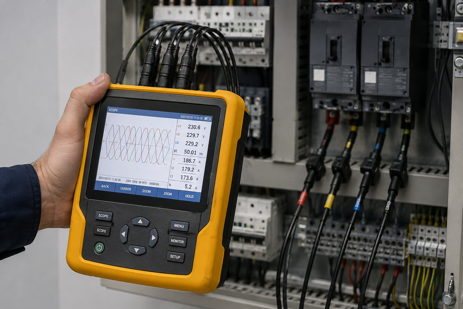
Die Dimensionierung eines aktiven Oberwellenfilters ist der Prozess der Bestimmung des erforderlichen Kompensationsstroms zur Entfernung unerwünschter Oberschwingungen aus einem elektrischen System.
Im Gegensatz zu Kondensatorbänken, die entsprechend der Blindleistung (kVAr) ausgewählt werden, wird ein aktiver Oberwellenfilter entsprechend dem in Ampere gemessenen Kompensationsstrom ausgewählt.
Ein aktiver Oberwellenfilter überwacht kontinuierlich die elektrische Wellenform und speist gleiche, aber entgegengesetzte Oberschwingungsströme in das System ein. Der eingespeiste Strom hebt den von nichtlinearen Lasten erzeugten Oberschwingungsstrom auf, bevor dieser sich im gesamten elektrischen Netz ausbreitet.
Eine korrekte Dimensionierung des aktiven Oberwellenfilters stellt sicher, dass der Filter über ausreichende Kapazität zur Kompensation vorhandener Oberschwingungsströme verfügt und gleichzeitig Spielraum für zukünftiges Lastwachstum bietet.
Eine falsche Dimensionierung des aktiven Oberwellenfilters ist einer der häufigsten Gründe für das Scheitern von Projekten zur Oberwellenminderung.
Wenn der Filter zu klein ist, bleibt die harmonische Verzerrung auch nach der Installation hoch. Transformatoren überhitzen weiterhin, Kondensatorbänke fallen weiterhin aus und empfindliche Geräte bleiben verzerrten Strömen ausgesetzt.
Wenn der Filter zu groß ist, kann sich die Oberwellenleistung verbessern, aber das Projekt wird unnötig teuer, ohne zusätzliche betriebliche Vorteile zu bieten.
Die korrekte Dimensionierung eines aktiven Oberwellenfilters bietet mehrere wichtige Vorteile:
Für die meisten Industrieanlagen ist eine genaue Dimensionierung der Unterschied zwischen einer dauerhaften Lösung des Oberwellenproblems und dem weiteren Auftreten wiederkehrender elektrischer Ausfälle.
Vor jeder Dimensionierung eines aktiven Oberwellenfilters müssen Ingenieure verstehen, was Oberschwingungsstrom tatsächlich ist.
Lineare elektrische Lasten beziehen einen gleichmäßigen sinusförmigen Strom aus der Netzversorgung.
Nichtlineare Lasten beziehen Strom in kurzen Impulsen statt in gleichmäßigen Sinuswellen. Diese Impulse erzeugen Oberschwingungsströme, die durch Transformatoren, Schaltanlagen, Kabel, Generatoren und Kondensatorbänke zirkulieren.
Zu den üblichen Geräten, die Oberschwingungen erzeugen, gehören:
Je mehr nichtlineare Lasten zu einer Anlage hinzugefügt werden, desto höher wird der Oberschwingungsstrom, wodurch die richtige Dimensionierung aktiver Oberschwingungsfilter zunehmend wichtiger wird.
Keine zwei elektrischen Systeme erzeugen identische Oberschwingungspegel. Mehrere Faktoren beeinflussen die erforderliche Filterkapazität.
Ein höherer Laststrom erzeugt im Allgemeinen einen höheren Oberschwingungsstrom. Der Gesamtstrom allein reicht jedoch niemals für die Dimensionierung aktiver Oberschwingungsfilter aus.
THDi gibt an, wie viel Oberschwingungsstrom im Verhältnis zum Grundstrom vorhanden ist.
Höhere THDi-Werte erfordern größere aktive Oberschwingungsfilter.
Verschiedene Geräte erzeugen unterschiedliche Oberschwingungsspektren.
Beispiel:
Das Verständnis der Lastzusammensetzung verbessert die Genauigkeit der Dimensionierung aktiver Oberschwingungsfilter.
Einige Fabriken arbeiten kontinuierlich nahe der Volllast.
Andere weisen im Laufe des Tages große Schwankungen auf.
Die Dimensionierung sollte den höchsten erwarteten Oberschwingungsstrom anstelle der durchschnittlichen Betriebsbedingungen berücksichtigen.
Viele Anlagen fügen innerhalb weniger Jahre neue Produktionslinien hinzu.
Die Auswahl eines modularen aktiven Oberschwingungsfilters ermöglicht zukünftige Erweiterungen, ohne das gesamte System auszutauschen.
Der erste Schritt bei der Dimensionierung aktiver Oberschwingungsfilter ist die Erfassung realer Betriebsdaten.
Ein Netzqualitätsanalysator sollte Folgendes messen:
Viele Projekte überspringen diesen Schritt und schätzen die Oberschwingungspegel nur anhand der Transformatorleistung.
Dies führt häufig zu einer falschen Filterdimensionierung, da Transformatornennwerte keinen tatsächlichen Oberschwingungsstrom anzeigen.
Nach der Messung des elektrischen Systems müssen die Ursprünge der Oberschwingungen identifiziert werden.
Typische Quellen sind:
Die Kenntnis des Standorts von Oberschwingungen erzeugenden Lasten hilft dabei zu bestimmen, ob ein zentraler oder verteilter Filteransatz geeigneter ist.
Der Kern der Dimensionierung von aktiven Oberschwingungsfiltern ist die Berechnung des Oberschwingungsstroms.
Die vereinfachte Gleichung lautet:
Oberschwingungsstrom = Laststrom × THDi
Beispiel:
Systemstrom = 800 A
Gemessene THDi = 30%
Oberschwingungsstrom:
800 × 30%
= 240 A
In diesem Beispiel erzeugt das elektrische System ungefähr 240 A Oberschwingungsstrom.
Normalerweise würde ein aktiver Oberschwingungsfilter mit einer Kompensationskapazität von etwa 250 A ausgewählt, wodurch eine kleine Auslegungsreserve berücksichtigt wird.
Diese Berechnung bildet die Grundlage der meisten Projekte zur Dimensionierung aktiver Oberschwingungsfilter.
Die gewünschte Oberschwingungsleistung beeinflusst den erforderlichen Kompensationsstrom.
Typische industrielle Zielwerte umfassen:
Eine niedrigere Zielverzerrung erfordert im Allgemeinen eine höhere Kompensationskapazität.
Anlagen zur Versorgung empfindlicher Geräte wählen häufig strengere Ziele zur Oberschwingungsreduzierung als schwere Industrieanlagen.
IEEE 519 ist eine der weltweit am häufigsten referenzierten Normen zur Oberschwingungsregelung.
Anstatt eine bestimmte Filtergröße festzulegen, definiert IEEE 519 zulässige Oberschwingungsgrenzwerte am Point of Common Coupling (PCC).
Eine korrekte Dimensionierung aktiver Oberschwingungsfilter hilft Anlagen, diese Grenzwerte einzuhalten und unnötige Investitionen zu vermeiden.
Bei der Entwicklung einer AHF-Lösung sollten Ingenieure die gemessene Oberschwingungsverzerrung immer mit den geltenden IEEE 519-Grenzwerten vergleichen, bevor sie Geräte auswählen.
Viele erfolglose Installationen entstehen durch einfache Fehler bei der Dimensionierung.
Zu den häufigsten gehören:
Die Transformatorgröße gibt den Oberschwingungsstrom nicht an.
Ein 2000-kVA-Transformator, der hauptsächlich lineare Lasten versorgt, benötigt möglicherweise nur wenig Oberschwingungskompensation, während ein 1000-kVA-Transformator, der zahlreiche Frequenzumrichter versorgt, möglicherweise einen wesentlich größeren Filter benötigt.
Ohne die Messung des THDi wird die Dimensionierung eines aktiven Oberschwingungsfilters zu kaum mehr als einer fundierten Schätzung.
Anlagen bleiben selten unverändert.
Das Hinzufügen weiterer Frequenzumrichter oder Produktionsanlagen erhöht den Oberschwingungsstrom im Laufe der Zeit.
Filter sollten entsprechend den maximal erwarteten Betriebsbedingungen dimensioniert werden.
Manchmal bieten mehrere kleinere Filter, die sich nahe an den Oberschwingungen erzeugenden Lasten befinden, eine bessere Leistung als ein einzelner zentraler Filter.
Eine wichtige Designentscheidung ist, wo der Filter installiert werden soll.
Vorteile:
Geeignet für Anlagen, bei denen Oberschwingungen erzeugende Lasten um eine Hauptschaltanlage konzentriert sind.
Vorteile:
Die dezentrale Filterung wird häufig für große Produktionsanlagen mit mehreren Fertigungsbereichen bevorzugt.
Eine ordnungsgemäße Dimensionierung aktiver Oberschwingungsfilter sollte sowohl den Kompensationsstrom als auch den Installationsort berücksichtigen.
Eine Produktionsanlage betreibt:
Messungen zeigen:
Berechneter Oberschwingungsstrom:
950 × 22 %
= 209 A
Nach der Überprüfung zukünftiger Erweiterungspläne wählen Ingenieure einen modularen aktiven Oberschwingungsfilter mit 250 A aus.
Nach der Inbetriebnahme:
Dieses Beispiel zeigt, warum die Dimensionierung eines aktiven Oberschwingungsfilters immer auf dem gemessenen Oberschwingungsstrom und nicht allein auf der Transformatorleistung basieren sollte.
Neben dem Kompensationsstrom sollten Ingenieure auch Folgendes bewerten:
Ein richtig ausgewählter aktiver Oberschwingungsfilter reduziert nicht nur heute Oberschwingungen, sondern unterstützt auch zukünftige Anlagenerweiterungen ohne umfangreiche Neugestaltung.



 IPv6-Netzwerk unterstützt