

 Deutsch
 English
 français
 español
 العربية
 中文
中文
Abnahmetest für aktive Oberschwingungsfilter: 5 kritische Schritte zur Kapazitätsüberprüfung und Inbetriebnahme vor Ort
Eine Bestellung beweist nicht, dass ein Aktiver Oberschwingungsfilter die Standortabnahme besteht. Das Projektteam muss bestätigen, was am Koppelpunkt des gemeinsamen Anschlusses (PCC) passiert, wenn Frequenzumrichter, Gleichrichter, Schweißgeräte, USV-Systeme und Kondensatorbänke gemeinsam betrieben werden.
Fordern Sie vor der Abnahme ein nachvollziehbares Nachweispaket an: gemessene Wellenformen, eine Kapazitätsberechnung, eine Netzsimulation, Prüfprotokolle und definierte Bestehens-/Nichtbestehenskriterien. Diese Dokumente machen eine angegebene Strombelastbarkeit zu einer technischen Verpflichtung.
Bitten Sie den Lieferanten, die Messungen zur Unterstützung des Angebots zu identifizieren: Spannung, Laststrom, THDi, THDv, Leistungsfaktor, Neutralleiterstrom, Oberschwingungsordnungen, Transformatorleistung und große nichtlineare Lasten.
Protokollieren Sie repräsentative Produktionszustände, nicht nur einen Durchschnittswert. Beziehen Sie Antriebsstarts, Schweißzyklen, Generatorbetrieb und Niedriglastperioden ein, in denen Kondensatorbänke überkompensieren können.
Definieren Sie den Abnahmepunkt PCC. Eine Messung mit geringer Verzerrung am Filterschrank weist keine Systemkonformität nach.
Dokumentieren Sie CT-Position und Übersetzungsverhältnis, Phasenfolge, Spannungsreferenz, Abtastintervall, Messgerätegenauigkeit und Methode zur Bedarfstrombestimmung.
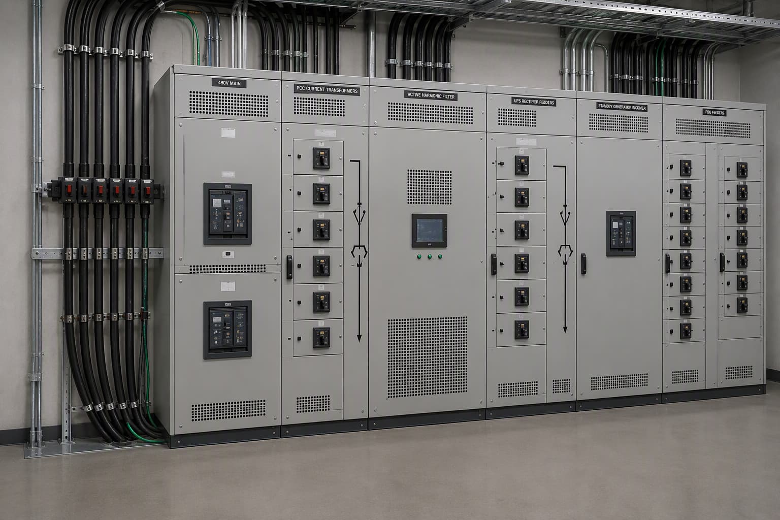
Ein 480-V-Hauptschaltfeld eines Rechenzentrums mit CTs am PCC, einem Schrank für aktive Oberschwingungsfilter, USV-Gleichrichterabgängen, einem Einspeisepunkt des Standby-Generators, PDU-Abgängen und einer THDi-Wellenform-Einblendung vor/nach der Kompensation. Kennzeichnen Sie den Messpfad, den Neutralleiter und den Abstand für die Wärmeabfuhr.
Die Nennleistung eines AHF muss dem Oberschwingungsstromspektrum und der erforderlichen Restverzerrung folgen, nicht allein der Nennleistung des Einspeiseschalters. Das Kapazitätsblatt sollte jede Lastgruppe, ihren Nennstrom, Diversitätsfaktor, gemessenes Oberschwingungsspektrum, erwarteten gleichzeitigen Betrieb, Ziel-THDi, ausgewählten Filterstrom und ungenutzte Erweiterungsreserve aufführen.
Für einen repräsentativen 480-V-Standort mit sechs-pulsigen Frequenzumrichterabgängen wird ein Spitzenoberschwingungsstrom von 180 A und ein Restziel von 50 A angenommen. Die erste Berechnung ergibt 130 A Kompensation vor Lastwachstum, Unsymmetrie, Blindstrombedarf und Temperaturreduzierung.
Geben Sie an, ob der AHF den Ausgangsstrom zwischen Oberschwingungsreduzierung, Blindleistungskompensation und Unsymmetriekorrektur aufteilt. Eine 150-A-Einheit kann nicht dauerhaft 150 A Oberschwingungsunterdrückung plus 150 A Blindstrom liefern.
Nullsystemströme erfordern in Dreiphasen-Vierleitersystemen besondere Aufmerksamkeit. Triplen-Oberschwingungen addieren sich im Neutralleiter statt sich aufzuheben, wodurch dieser überhitzen kann, selbst wenn der Phasenstrom akzeptabel erscheint.
Zeigen Sie Phasen- und Neutralleiterstrom vor und nach der Kompensation. Geben Sie bei Bedarf eine Vierleitertopologie und deren Grenzwert für die kontinuierliche Neutralleiterkompensation an.
|
Technische Frage |
Passiver Filter / Kondensatorbank |
Aktiver Oberschwingungsfilter |
SVG |
|
Primäre Stromfunktion |
Abgestimmte Oberschwingungsabsorption oder feste/gestufte Blindleistung |
Speist kompensierende Oberschwingungs-, Unsymmetrie- und optionale Blindströme ein |
Speist dynamischen grundfrequenten Blindstrom ein |
|
Beste Eignung |
Stabiles Oberschwingungsspektrum und gleichmäßige Last |
Frequenzumrichter, Gleichrichter, USV, Schweißbetrieb oder wechselndes Oberschwingungsspektrum |
Schnelle Leistungsfaktorkorrektur und Spannungsunterstützung |
|
Reaktion auf Oberschwingungsspektrum |
Nur um abgestimmte Ordnungen wirksam; Resonanzprüfung erforderlich |
Breitbandige Kompensation hängt von Reglereinstellungen und Stromkapazität ab |
Ersetzt keine Kapazität zur Oberschwingungsreduzierung |
|
Stromzuweisung |
Der Kondensatorstrom wird durch Spannung und Stufen der Bank festgelegt |
Eine einzige Umrichterstromgrenze wird zwischen aktivierten Funktionen geteilt |
Der Umrichterstrom wird der Blindleistungskompensation zugewiesen |
|
Abnahmenachweise |
Abstimmungsstudie, Daten des Entdrosselungsreaktors, Resonanzprüfung |
PCC-Trend, Ergebnis der Oberschwingungsordnung, Ausgangsstromtrend, thermischer Test |
Leistungsfaktortrend, kvar-Reaktion, Spannungstrend |
Die Simulation sollte die Impedanz von Quelle und Transformator, Kabel, Kondensatorbänke, Generatoren (falls zutreffend), das Spektrum nichtlinearer Lasten, die Hintergrundspannung und die vorgeschlagenen AHF/SVG-Einstellungen modellieren.
Überprüfen Sie den normalen Produktionsbetrieb, die maximale nichtlineare Last und den Betrieb der Kondensatoren bei geringer Last. Fügen Sie den Generatormodus hinzu, falls zutreffend, da dessen unterschiedliche Reaktanz die Verzerrung und das Schutzverhalten verändern kann.
Zeigen Sie PCC THDi/THDv, Oberschwingungsordnungen, Leistungsfaktor, Spannungsschwankung, Filterstrom und Reserve an. Geben Sie an, was passiert, wenn der Filter seine Dauerstromgrenze erreicht.
Prüfen Sie die Resonanz, bevor Sie Kondensatorbänke beibehalten. Ihre Wechselwirkung mit der Netzinduktivität kann ausgewählte Ordnungen verstärken und die Lebensdauer von Kondensatoren, Schützen, Kabeln und Leistungsschaltern verkürzen.
Eine 3-Level-Topologie erzeugt kleinere Spannungsschritte als ein vergleichbarer 2-Level-Wandler. Dies kann die dv/dt-Belastung reduzieren, während Verluste und thermisches Verhalten weiterhin von Schaltfrequenz, Modulation, Kühlung und Laststrom abhängen.
Die SPWM-Modulation erzeugt einen kompensierenden Strom. Fordern Sie den Schaltfrequenzbereich, die Regelbandbreite, die Auswahl der Oberschwingungsordnungen, die CT-Abtastanordnung und das Verhalten bei wechselnder Last an.
Fordern Sie eine thermische Erklärung an, die den kontinuierlichen Ausgang bei angegebener Umgebungstemperatur, Höhe, Gehäuse, Wärmeableitung, Luftstrom, Freiraum und Leistungsreduzierung abdeckt.
Bei 45 °C Umgebungstemperatur unter Volllast werden IGBT- oder SiC-MOSFET-Verluste zu Gehäusewärme. Unzureichende Kühlung erhöht die Sperrschichttemperatur, verkürzt die Bauteillebensdauer und kann eine Reduzierung des Ausgangsstroms erzwingen.
Werkseitige Aufzeichnungen sollten Seriennummer, elektrische Nennwerte, Isolations- und Funktionsprüfungen, Schutz- und Kommunikationstests sowie den Umfang der Lastprüfung ausweisen. Werkstests stellen den Gerätezustand fest; die Inbetriebnahme überprüft das Netzergebnis.
Der Inbetriebnahmeplan sollte CT-Polarität, Phasenfolge, Schutzprüfung, Alarm- und Stufenlasttests, Protokollierungsdauer, Analysatorstandort und Berichtfreigabe definieren.
|
Standortbedingung |
Vor der Genehmigung erforderliche Nachweise |
Typische Konfigurationslogik |
Abnahmemessgröße am Standort |
|
480-V-Rechenzentrum mit hoher UPS-Nutzung |
UPS-Gleichrichterprofil; PDU-Belastung; Transformator- und Generatordaten |
Vierleiter-AHF bei vorhandenem Triplen-Strom; Kapazität basierend auf dem maximalen UPS-Oberschwingungsstrom |
PCC THDi/THDv-Trend, Reduzierung des Neutralleiterstroms und keine UPS- oder Generatoralarme |
|
Generatorgestützter Rechenzentrumsbus |
Umschaltsequenz, Generatorreaktanz, UPS-Betriebsmodus und Lastsprungaufzeichnung |
Generatormodus simulieren; AHF-Stromgrenze mit UPS- und Generatorschutz koordinieren |
Stabile Umschaltung, Filterstromreserve und keine definierten Fehlauslösungen des Schutzes |
|
Vorhandene Kondensatorbank mit Fehlauslösungen |
Kondensatorstufen, Drosseldaten, Oberschwingungsordnungsscan, Schutzverlauf |
Resonanzbewertung; Kondensatorbank mit AHF/SVG beibehalten, verstimmen, isolieren oder koordinieren |
Keine resonanzbedingten Alarme oder Überströme während definierter Betriebsfälle |
|
45 °C warmer Innenraum für elektrische Anlagen |
Raumtemperaturprotokoll; Lüftungslayout; Anforderungen an Höhe und Gehäuse |
Dauerstrom mit Leistungsreduzierung und Wärmeabfuhr des Schranks vor der endgültigen AHF-Auslegung überprüfen |
Kontinuierlicher Ausgangsstrom und interner Temperaturtrend während des Lasttests |
|
Generatorgestützter Industrieanlagenbus |
Generatornennleistung, Reaktanz, Umschaltsequenz, Profil der nichtlinearen Last |
Generatormodus simulieren; AHF/SVG-Stromgrenzen und Schutzeinstellungen koordinieren |
Stabiler Betrieb während der Umschaltung und keine definierten Fehlauslösungen des Schutzes |
Ein repräsentatives nordamerikanisches Rechenzentrum betrieb ein 480-V-Verteilungssystem mit USV-Gleichrichtereingängen, PDU-Einspeisungen, IT-Stromversorgungen und Notstromgeneratoren. Das Engineering-Team musste harmonische Belastungen und Risiken durch Neutralleiterströme verhindern und gleichzeitig einen stabilen Betrieb während der Generatorumschaltung gewährleisten.
Der Lieferant erfasste PCC-Spannung und -Strom während des normalen USV-Betriebs, bei stufenweisen Laständerungen, Batterieladung und Generatorumschalttests. Die Aufzeichnungen prüften einzelne Oberschwingungsordnungen, Neutralleiterstrom, Transformatorbelastung, USV-Betriebsmodus und Verzerrung, wenn die Generatorquellimpedanz die Netzquellimpedanz ersetzte.
Der Vorschlag verwendete einen vieradrigen aktiven Oberschwingungsfilter, der anhand des beobachteten maximalen Oberschwingungsstroms mit definiertem Erweiterungsspielraum dimensioniert wurde. Die Berechnung reservierte Stromkapazität für die Oberschwingungsreduzierung und die Neutralleiterstromkompensation, anstatt anzunehmen, dass derselbe Umrichterstrom gleichzeitig für jede aktivierte Funktion verfügbar ist.
Die Inbetriebnahmeabnahme verwendete PCC-Vorher/Nachher-Trends, Daten zu Oberschwingungsordnungen, Neutralleiterstromaufzeichnungen, AHF-Ausgangsstrom, USV-Alarmhistorie und Beobachtungen der Generatorumschaltung. Das erforderliche Ergebnis war das vereinbarte PCC-Ziel über alle aufgezeichneten Betriebsmodi des Rechenzentrums hinweg ohne AHF-Strombegrenzungsereignisse, USV-Alarme oder definierte Fehlauslösungen des Schutzes.
Die Kapazität sollte auf dem gemessenen maximalen Oberschwingungsstrom, dem Zielwert für den verbleibenden Oberschwingungsstrom, dem Verhalten bei gleichzeitiger Last, den aktivierten Funktionen, der Temperaturreduzierung und einer dokumentierten Wachstumsreserve basieren. Der Lieferant sollte die vollständige Stromzuweisungsberechnung vorlegen, anstatt ein Gerät allein anhand der Transformator-kVA auszuwählen.
Die Antwort hängt von der Schaltanlagenarchitektur, der Verfügbarkeit einer Reserveeinspeisung, dem Trennverfahren und der Installationsmethode der Stromwandler ab. Lieferanten sollten eine Arbeitsanweisung bereitstellen, die Arbeiten mit erforderlicher Spannungsfreischaltung von Konfigurations- und Inbetriebnahmetätigkeiten trennt, die nach der Wiederherstellung durchgeführt werden können.
Sie erfordern geplante Inspektionen von Luftwegen, Lüftern, gegebenenfalls Filtern, Anschlüssen, Alarmhistorie, Kommunikationsverbindungen und aufgezeichneten Betriebstemperaturen. Der Wartungsplan sollte Inspektionsintervalle auf Grundlage von Umgebungsstaub, Temperatur, Lastprofil und Gehäusedesign festlegen, anstatt eine allgemeine Kalenderangabe zu verwenden.
Es kann für diese Systeme ausgelegt werden, aber der Vorschlag muss deren Impedanz, Betriebsmodi, Schutzeinstellungen und harmonische Wechselwirkungen in der Studie berücksichtigen. Akzeptieren Sie keine Kompatibilitätserklärung ohne Prüfung des Einliniendiagramms und Annahmen zu den Betriebsfällen.
Ein Angebot für einen aktiven Oberschwingungsfilter wird glaubwürdig, wenn der Lieferant eine gemessene Ausgangsbasis, eine transparente Kapazitätsberechnung, eine Simulation der Betriebsfälle, thermische Grenzwerte, Werksnachweise und PCC-Inbetriebnahmekriterien bereitstellt. Dieses Paket schützt den Käufer vor einem Gerät, das zwar korrekt dimensioniert erscheint, aber die Stromgrenze erreicht, bei hoher Umgebungstemperatur Ausgangsleistung verliert oder das gemessene Netzproblem nicht behebt.
YT Electric kann das Einliniendiagramm, das Lastprofil, die Oberschwingungsdaten, die Umgebungsbedingungen und das Abnahmeziel vor der endgültigen Festlegung einer AHF-, SVG- oder STATCOM-Konfiguration prüfen. Beginnen Sie mit den für Ihr Projekt erforderlichen Nachweisen und wählen Sie anschließend den Gerätestrom und die Topologie aus, die das erforderliche Ergebnis nachweisen können.
Entdecken Sie die Produktspezifikationen und Anwendungshinweise von YT Electric: https://www.ytelect.com/blog/guide-to-selecting-active-harmonic-filters_b321
Referenz: IEEE 519-2022, IEEE-Standard zur Oberschwingungsregelung in elektrischen Energiesystemen: https://standards.ieee.org/ieee/519/10677/
Benötigen Sie eine standortspezifische Lösung? Teilen Sie Ihr Einliniendiagramm, Ihre Lastliste, den gemessenen Leistungsfaktor, THDi/TDD-Daten und Umgebungsbedingungen mit YT Electric. Unsere Vertriebsingenieure können die Daten prüfen und einen technischen Vorschlag erstellen.



 IPv6-Netzwerk unterstützt